Map Toolbar

Layers
 give users the ability to change the background map on the
map display. These include Street Map, Satellite,
Satellite with Labels,
Google Map, Google Satellite, Google Hybrid, Google
Terrain, Google Roads, IFR Enroute Low Charts, Dark with Labels, Dark No Labels,
Light with Labels and Light No Labels.
give users the ability to change the background map on the
map display. These include Street Map, Satellite,
Satellite with Labels,
Google Map, Google Satellite, Google Hybrid, Google
Terrain, Google Roads, IFR Enroute Low Charts, Dark with Labels, Dark No Labels,
Light with Labels and Light No Labels.
Geo Widgets
 allow users to incorporate overlays onto their map display
which include FAA UAS Facility Map, National Flight
Restrictions, Recreational Flyer Fixed Sites, Drone
Classifications, TFRs, Microweather, FAA Recognized
Identification Areas, Open AIP Maps. Additionally, Geo Widgets
allow users to remove the aircraft icon colors by altitude,
hide flights below 5000ft and overlay weather.
allow users to incorporate overlays onto their map display
which include FAA UAS Facility Map, National Flight
Restrictions, Recreational Flyer Fixed Sites, Drone
Classifications, TFRs, Microweather, FAA Recognized
Identification Areas, Open AIP Maps. Additionally, Geo Widgets
allow users to remove the aircraft icon colors by altitude,
hide flights below 5000ft and overlay weather.
The Sensors icon
 allows users to toggle sensors displays and sensor detection
ranges on the map. It also enables the user to turn on or off
aircraft tracks based on the detection device and aircraft
type.
allows users to toggle sensors displays and sensor detection
ranges on the map. It also enables the user to turn on or off
aircraft tracks based on the detection device and aircraft
type.
The Tools
 menu allows users to measure lines and polygons using the
Ruler tool, revert the map display to a previous point in time
(‘Time Machine’), and Toggle CUI classification header at the
top of the COP. It also includes additional features such as
Toggle Serial, which censors all drone serial numbers across
flight profiles, and Toggle Geozones, allowing users to select
and display user-defined geozones on the COP map.
Additionally, the Share My Location feature lets users
publicly share their current location with the COP and display
it on the map in real time
menu allows users to measure lines and polygons using the
Ruler tool, revert the map display to a previous point in time
(‘Time Machine’), and Toggle CUI classification header at the
top of the COP. It also includes additional features such as
Toggle Serial, which censors all drone serial numbers across
flight profiles, and Toggle Geozones, allowing users to select
and display user-defined geozones on the COP map.
Additionally, the Share My Location feature lets users
publicly share their current location with the COP and display
it on the map in real time

The Ruler
 tool measures the distance between points on the ground and
provides a heading. Users can measure using either a line or
a polygon
tool measures the distance between points on the ground and
provides a heading. Users can measure using either a line or
a polygon
- Line:
- Displays the distance in units such as miles, nautical miles, kilometers, feet, or meters, and the heading in degrees or radians.
- To use, click once to start the line and click again to end it.
- Polygon:
- Displays the perimeter in miles, nautical miles, kilometers, feet, or meters and the area in square miles, square nautical miles, square kilometers, square feet, or square meters.
- Click once to initiate an edge and continue clicking to add more edges. Clicking back on the original edge connects and completes the polygon.
Toggle Geozones
 when pressed opens a list of user-defined geozones. From
this list, users can select the geozones they wish to
display on the COP map.
when pressed opens a list of user-defined geozones. From
this list, users can select the geozones they wish to
display on the COP map.
Set Map Center
![]() tool allows users to reposition the COP (Common Operating Picture) map around a chosen location, helping maintain focus
on areas of interest.
tool allows users to reposition the COP (Common Operating Picture) map around a chosen location, helping maintain focus
on areas of interest.
Steps to set a new map center:
![]() button.
button.
Import KML/KMZ
![]() allows users to upload and display custom KML or
KMZ
files directly on the
COP (Common Operating Picture) map.
These files can include items such as geofences,
flight paths, or area boundaries, providing
additional spatial context during operations. Once
imported, the data layers are rendered on the COP
for enhanced situational awareness and mission
planning.
allows users to upload and display custom KML or
KMZ
files directly on the
COP (Common Operating Picture) map.
These files can include items such as geofences,
flight paths, or area boundaries, providing
additional spatial context during operations. Once
imported, the data layers are rendered on the COP
for enhanced situational awareness and mission
planning.
Users can click
“Select KML or KMZ file”
to browse and select a file for import. Once
uploaded, the file is rendered on the COP map for
immediate visualization. Once a file is selected,
click
IMPORT
to upload it to the COP or
CANCEL
to discard the action.
After importing, the
file name
appears in a list below the tool. Each imported file
can be toggled on or off, allowing users to control
the visibility of individual KML/KMZ layers as
needed.
Change Language
![]() tool allows users to display UNIFY.C2 in an
alternative language for accessibility and ease of
use.
tool allows users to display UNIFY.C2 in an
alternative language for accessibility and ease of
use.
When clicked, it opens a dropdown menu listing
supported languages. Selecting a language immediately
updates all system text within UNIFY.C2 to that
language.
Note:
As of
AUG 2025, only two languages are available within UNIFY.C2:
English
and
Spanish.
Filter Radar Tracks
 allows users to automatically filter out radar
tracks that are likely caused by wind-blown debris
or other non-aircraft sources moving with the
wind.
allows users to automatically filter out radar
tracks that are likely caused by wind-blown debris
or other non-aircraft sources moving with the
wind.
Users can define the filtering criteria using the
following inputs:
If a radar track matches all these conditions, it
will automatically be hidden from the COP, helping
reduce clutter and focus attention on more relevant
targets.
Time Machine
 allows users to revert the map display and aircraft tracks to
a previous point in time for analysis. Users can specify a
date and time, control playback, and adjust the speed of the
replay
allows users to revert the map display and aircraft tracks to
a previous point in time for analysis. Users can specify a
date and time, control playback, and adjust the speed of the
replay
Selecting a Date and Time:
- Click inside the Start Time field.
-
Click the Calendar icon
 to open the date picker.
- Select a date and close the popup.
- To remove the date, click the selected date again.
-
Click the Clock icon
 to set the time.
- Select the hour (in 12-hour format), then select minutes, and close the popup.
- The selected time will be displayed in 24-hour format.
- To clear the Start Time field, click inside the field and press Backspace on the keyboard.
Controlling Playback:
-
Play/Pause
 – Click to toggle between start or pause playback.
-
Restart
 – Click to reset playback to the selected Date and Time.
- Playback Speed – Select 1X (normal speed) or 5X (five times normal speed).
Managing the Time Machine Panel:
-
Minimize
 – Click to hide the panel while keeping Time Machine
active.
– Click to hide the panel while keeping Time Machine
active.
-
Close
 – Click to exit Time Machine and return the map to the
current Date and Time.
– Click to exit Time Machine and return the map to the
current Date and Time.
Share My Location
 when pressed, will publicly share your location with the
COP. Once activated, your location will be displayed on
the map in real time, allowing the COP to see your
position.
when pressed, will publicly share your location with the
COP. Once activated, your location will be displayed on
the map in real time, allowing the COP to see your
position.
Toggle CUI
 option allows users to show or hide the Controlled
Unclassified Information (CUI) classification headers
displayed at the top and bottom of the COP (Common
Operating Picture). This can help declutter the interface
when classification markings are not needed for
situational awareness.
option allows users to show or hide the Controlled
Unclassified Information (CUI) classification headers
displayed at the top and bottom of the COP (Common
Operating Picture). This can help declutter the interface
when classification markings are not needed for
situational awareness.
Note: These toggles are session-based and do not persist across page refreshes. Users must re-enable them each time the page reloads.
Toggle Serial
 option, when activated, censors all drone serial numbers
across the COP, including within flight profiles. This is
useful for demonstrations or when sensitive identifiers
should remain hidden.
option, when activated, censors all drone serial numbers
across the COP, including within flight profiles. This is
useful for demonstrations or when sensitive identifiers
should remain hidden.
Note: These toggles are session-based and do not persist across page refreshes. Users must re-enable them each time the page reloads.
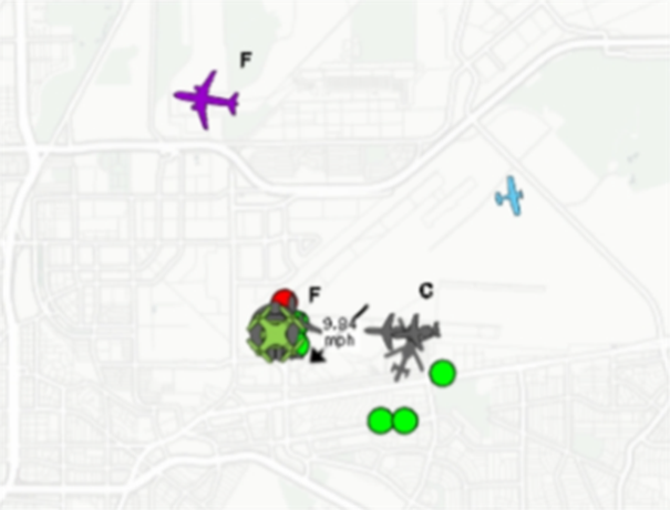
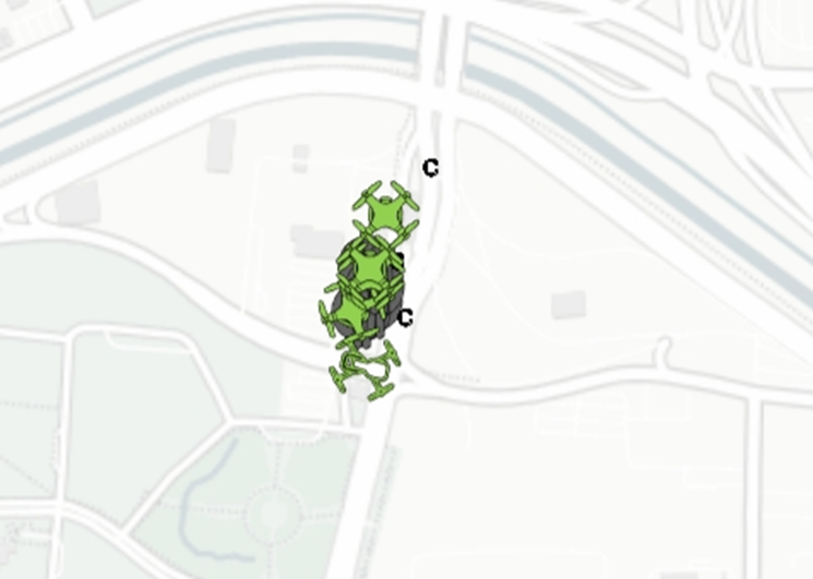
Dynamic Display of C/F
 tool controls the visibility of Correlation (C) and Fusion
(F) markers for aircraft tracks within the COP (Common
Operating Picture).
tool controls the visibility of Correlation (C) and Fusion
(F) markers for aircraft tracks within the COP (Common
Operating Picture).
When enabled, the COP will dynamically display or hide
the C (Correlation) and F (Fusion) indicators based on the
activity status of the associated tracks.
If one of the correlated or fused tracks becomes inactive,
its corresponding C or F marker will no longer be
displayed.
DAA Mode
 enables the COP’s Detect And Avoid Mode, which filters the
COP display to show only low-altitude aircraft. It also
highlights the detection ranges for site EOs. The radius
turns red when aircraft come into close proximity with one
another, indicating a potential conflict.
enables the COP’s Detect And Avoid Mode, which filters the
COP display to show only low-altitude aircraft. It also
highlights the detection ranges for site EOs. The radius
turns red when aircraft come into close proximity with one
another, indicating a potential conflict.
When toggled, Fusion
 processes data from different asset classes—such as radar
and ADS-B—to generate a single, unified track for each
aircraft. This allows the system to combine insights from
multiple detection types into a more accurate
representation.
processes data from different asset classes—such as radar
and ADS-B—to generate a single, unified track for each
aircraft. This allows the system to combine insights from
multiple detection types into a more accurate
representation.
Fusion automatically enables Correlation if not already
active.
When toggled, Correlation
 cross-references aircraft data detected by multiple
sensors within the same asset class to prevent duplication
and ensure proper track consolidation.
cross-references aircraft data detected by multiple
sensors within the same asset class to prevent duplication
and ensure proper track consolidation.
When activated, Pilot Mode
 allows users to monitor a specific aircraft by
configuring proximity warning thresholds and selecting
how the aircraft is identified. This tool enhances
situational awareness and helps prevent potential
airspace conflicts by issuing alerts when nearby
activity exceeds user-defined safety margins.
allows users to monitor a specific aircraft by
configuring proximity warning thresholds and selecting
how the aircraft is identified. This tool enhances
situational awareness and helps prevent potential
airspace conflicts by issuing alerts when nearby
activity exceeds user-defined safety margins.
Users
can identify the monitored aircraft in one of two ways:
Tail Number
When identifying the aircraft via Tail Number, users
can:
- Enter the aircraft tail number
- Input the projected flight time
- Define the horizontal warning distance
- Set the vertical warning distance
- Enable visual and audio alerts on the COP
- Ignore string EO tracks to streamline the display
Device Location
When using the user’s current device location to
associate an aircraft, users can:
Note:
Additional options:
Pilot Mode is especially valuable for maintaining awareness around high-priority or nearby aircraft during operations, training, or deconfliction scenarios.
Sensor Display – Fixed
 toggle allows users to pin the sensor list to the
bottom of the COP (Common Operating Picture) for easy
and consistent access.
toggle allows users to pin the sensor list to the
bottom of the COP (Common Operating Picture) for easy
and consistent access.
When activated:

The Map Reset
 function allows users to quickly reset the zoom level on
the map and center the map display on the area of
responsibility (AOR).
function allows users to quickly reset the zoom level on
the map and center the map display on the area of
responsibility (AOR).
Center On My Location
 centers the COP map on your current location.
Orient North
 when toggled keeps the top of the COP map oriented towards
north.
when toggled keeps the top of the COP map oriented towards
north.
Zoom In & Zoom Out
-
Zoom In
 - Increases the zoom level on the map for a closer view
of aircraft tracks and geographic details.
- Increases the zoom level on the map for a closer view
of aircraft tracks and geographic details.
-
Zoom Out
 - Decreases the zoom level on the map for a broader
view of airspace activity.
- Decreases the zoom level on the map for a broader
view of airspace activity.